


Cookies help us deliver our services. By using our services, you agree to our use of cookies.
Chapter 3. Electrical Characteristics (The Physical Layer)
3.1 Data Encoding: Manchester II Bi-Phase
Unlike standard commercial serial protocols (like RS-232 or SPI) which use Non-Return-to-Zero (NRZ) encoding, MIL-STD-1553 uses Manchester II Bi-Phase Level encoding.
In Manchester encoding, data is not defined by a voltage level (high or low), but by the direction of the transition at the center of the bit period.
- Logic 0: A transition from High to Low.
- Logic 1: A transition from Low to High.
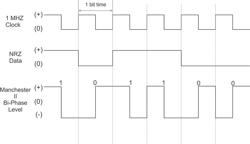
Figure 5 - Data Encoding - Manchester II bi-phase level vs. NRZ Encoding
Why Manchester II?
- Self-Clocking: The transition at the center of every bit allows the receiver to synchronize its internal clock with the incoming data stream, eliminating the need for a separate clock line.
- Zero DC Component: Because every bit contains both a positive and negative pulse of equal duration, the signal has no DC component. This is critical because it allows the signal to pass through isolation transformers, which block DC currents.
3.2 Transmission Medium
The standard specifies a shielded twisted pair cable with specific impedance and shielding characteristics to ensure signal integrity.
Table 1 - MIL-STD-1553B Cable Characteristics
| Parameter | Specification |
| Cable Type | Shielded Twisted Pair (STP) |
| Characteristic Impedance (Z0) | 70Ω to 85Ω (at 1.0 MHz) |
| Capacitance | 30.0 pF/ft maximum (wire-to-wire) |
| Cable Attenuation | 1.5 dB/100 ft maximum (at 1.0 MHz) |
| Twist Ratio | 4 twists per foot minimum |
| Shield Coverage | 90% minimum (Notice 2 requirement) |
3.3 Coupling Methods
Connecting a device to the main bus "backbone" is called stubbing. The standard defines two methods for this connection: Transformer Coupling and Direct Coupling.
3.3.1 Transformer Coupling (Preferred)
Transformer coupling is the industry standard for most avionics applications. It connects the terminal to the main bus via a stub that uses an isolation transformer.
- Stub Length: Up to 20 feet (6.1 meters).
- Components: Requires a stub coupler box containing a 1:1.41 turns ratio transformer and two isolation resistors (0.75 Z0)
- Advantages: Provides excellent galvanic isolation, improved common-mode rejection, and better impedance matching.
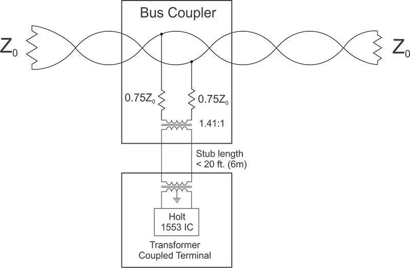
Figure 6 - Transformer Coupled Stub Connection
3.3.2 Direct Coupling
Direct coupling connects the terminal directly to the bus without an external stub coupler transformer.
- Stub Length: Strictly limited to 1 foot (30 cm) maximum.
- Use Case: Only used when the device is physically located immediately adjacent to the main bus cable.
- Risk: A short circuit in the terminal or stub can potentially disable the entire bus segment.
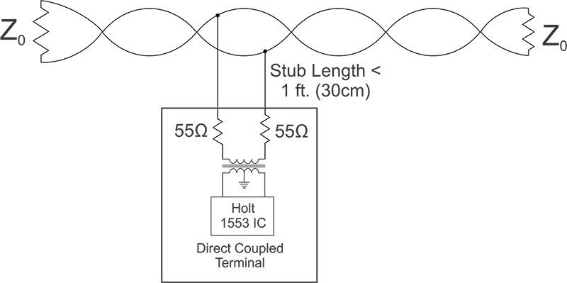
Figure 7 - Direct Coupled Bus Connection.

Figure 8 - Holt HI-6138 coupling showing direct vs. transformer coupled bus connection.
3.4 Terminal Input/Output Characteristics
MIL-STD-1553B defines strict electrical limits for terminal Inputs and Outputs to ensure interoperability across different manufacturers. These values differ depending on whether the terminal is using Transformer Coupling or Direct Coupling.
3.4.1 Output Characteristics
The terminal must be able to drive the bus within specific voltage ranges and waveform characteristics. The standard mandates a specific trapezoidal shape to minimize electromagnetic interference (EMI) while ensuring reliable detection.
- Output Levels (Peak-to-Peak, Line-to-Line):
- Transformer Coupled: 18.0 to 27.0 Volts.
- Direct Coupled: 6.0 to 9.0 Volts.
- Zero Crossing Deviation (ZCD): * The waveform must cross zero within ±25 ns of the ideal zero crossing point.
- Note: This is measured from the previous zero crossing (the 500ns, 1000ns, 1500 ns, or 2000 ns intervals).
- Waveform Shape:
- Rise/Fall Time: The signal must transition between 10% and 90% of the peak amplitude within 100 ns to 300 ns.
- Distortion: Overshoot and ringing must not exceed ±900 mV for transformer coupled (or ±300 mV for direct coupled).
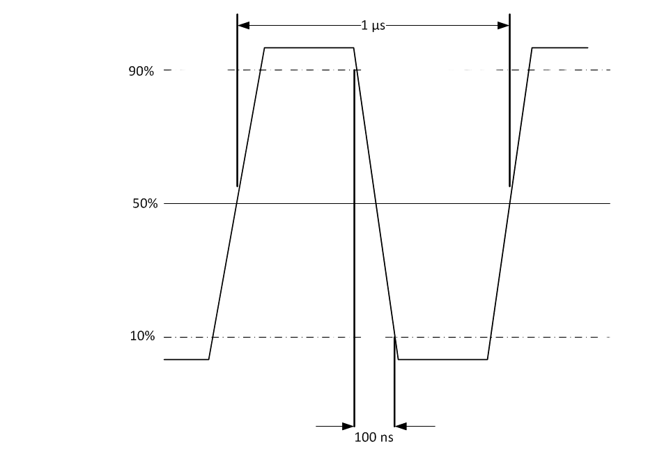
Figure 9 - Output Waveform Characteristics.
(Note: This diagram illustrates the trapezoidal pulse, detailing the 18-27V amplitude, the 100-300ns rise/fall times, and the ±25 ns zero-crossing stability window.)
- Output Symmetry:
- The standard requires that the positive and negative half-cycles match closely to prevent DC offset accumulation, which could saturate the coupling transformers.
- Specification: The difference in peak amplitude between the positive and negative portions of the waveform shall not exceed ±250 mV (for transformer coupled stubs).
- End of Message: This specification is particularly critical at the end of a transmission sequence to ensure the bus returns to a quiescent state without significant residual DC imbalance.
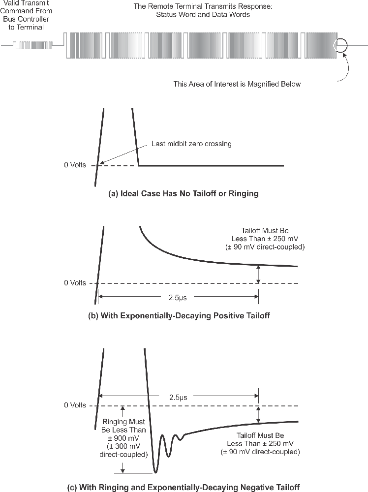
Figure 10 - Output Symmetry Characteristics.
(Note: Diagram showing the comparison of positive and negative peak amplitudes and the symmetry requirements at the end of the message sequence.)
3.4.2 Input Characteristics
The terminal receiver must be robust enough to decode signals that may have degraded while traveling down the bus, while rejecting noise and common mode interference.
- Input Impedance:
- The impedance looking into the terminal must be high enough not to load down the bus.
- Transformer Coupled: Greater than 1000Ω over the frequency range of 75 kHz to 1.0 MHz.
- Direct Coupled: Greater than 2000Ω over the frequency range of 75 kHz to 1.0 MHz.
- Receiver Thresholds (Response/No-Response): The receiver must discriminate between valid signals and low-level noise.
- Transformer Coupled:
- Must Respond: 0.86 V to 14.0 V peak-to-peak.
- Must Not Respond: 0.0 V to 0.20 V peak-to-peak.
- Direct Coupled:
- Must Respond: 1.2 V to 20.0 V peak-to-peak.
- Must Not Respond: 0.0 V to 0.28 V peak-to-peak.
- Transformer Coupled:
- Common Mode Rejection (CMR):
- The receiver must operate without error in the presence of common mode signals (signals appearing on both lines relative to ground).
- Specification: ±10 Volts peak, in the range of DC to 2.0 MHz.
- Waveform Compatibility: The receiver must accept waveforms varying from a square wave to a sine wave.
- Zero Crossing Tolerance: It must correctly decode signals even if the zero crossing deviates by up to ±150 ns.
3.4.3 Noise Rejection
A critical requirement for military avionics is the ability to operate in noisy electrical environments. The standard mandates a rigorous Noise Rejection Test.
- Requirement: The terminal must exhibit a maximum word error rate of one part in 107 on all words received by the terminal.
- Test Condition: This is measured while receiving valid messages in the presence of additive white Gaussian noise distributed over a bandwidth of 1.0 kHz to 4.0 MHz at an RMS amplitude of 140 mV (Transformer Coupled) or 200mV (Direct Coupled).
- The word error rate shall be measured with a 2.1 V (3.0V Direct Coupled) peak-to-peak, line-to-line, input to the terminal.
No. of Errors | Reject (Equal or less) | Accept (Equal or more) |
| 0 | N/A | 4.40 |
| 1 | N/A | 5.21 |
| 2 | N/A | 6.02 |
| 3 | N/A | 6.83 |
| 4 | N/A | 7.64 |
| 5 | N/A | 8.45 |
| 6 | 0.45 | 9.27 |
| 7 | 1.26 | 10.08 |
| 8 | 2.07 | 10.89 |
| 9 | 2.88 | 11.70 |
| 10 | 3.69 | 12.51 |
| 11 | 4.50 | 13.32 |
| 12 | 5.31 | 14.13 |
| 13 | 6.12 | 14.94 |
| 14 | 6.93 | 15.75 |
| 15 | 7.74 | 16.56 |
| 16 | 8.55 | 17.37 |
| 17 | 9.37 | 18.19 |
| 18 | 10.18 | 19.00 |
| 19 | 10.99 | 19.81 |
| 20 | 11.80 | 20.62 |
| 21 | 12.6 | 21.43 |
| 22 | 13.42 | 22.24 |
| 23 | 14.23 | 23.05 |
| 24 | 15.04 | 23.86 |
| 25 | 15.85 | 24.67 |
| 26 | 16.66 | 25.48 |
| 27 | 17.47 | 26.29 |
| 28 | 18.29 | 27.11 |
| 29 | 19.10 | 27.92 |
| 30 | 19.90 | 28.73 |
| 31 | 20.72 | 29.54 |
| 32 | 21.53 | 30.35 |
| 33 | 22.34 | 31.16 |
| 34 | 23.15 | 31.97 |
| 35 | 23.96 | 32.78 |
| 36 | 24.77 | 33.00 |
| 37 | 25.58 | 33.00 |
| 38 | 26.39 | 33.00 |
| 39 | 27.21 | 33.00 |
| 40 | 28.02 | 33.00 |
| 41 | 33.00 | N/A |
Figure 11 - Noise Rejection Test Criteria (Accept or Reject)
3.5 The Holt Advantage: Integrated Transformers
One of the biggest challenges in MIL-STD-1553 design is the physical board space required for the isolation transformers and transceivers. In a traditional design, the protocol logic, transceiver, and transformer are all separate, bulky components.
Holt Integrated Circuits has revolutionized this physical layer implementation.
3.5.1 Integrated Transceivers (HI-25850)
The HI-25850 is a single supply 3.3V dual transceiver that integrates the isolation transformers directly into the IC package.
- Benefit: Eliminates the need for an external transformer, significantly reducing the Component on Board (COB) area.
- Compliance: Fully compliant with MIL-STD-1553A/B, MIL-STD-1760, and McAir A3818.
3.5.2 Integrated Terminals (HI-2130)
For a complete terminal solution, the HI-2130 combines the protocol logic, shared RAM w/ Error-Correcting Codes (ECC), dual transceivers, AND the isolation transformers into a single compact BGA package.
- Zero-Component Interface: It connects directly to the bus coupler, requiring no external isolation transformers.
- Reliability: By moving the magnetics inside the IC, the interface is protected and optimized for signal integrity, reducing design risk for the engineer.
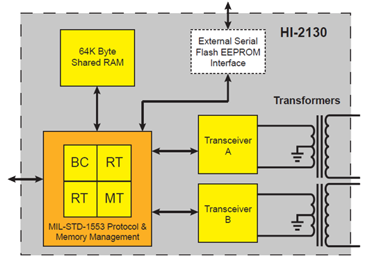
Figure 12 - HI-2130 Block Diagram (Note: Internal isolation transformers connect to the bus pins.)
Chapter 4.